File:Fig1.png

Original file (1,043 × 855 pixels, file size: 291 KB, MIME type: image/png)
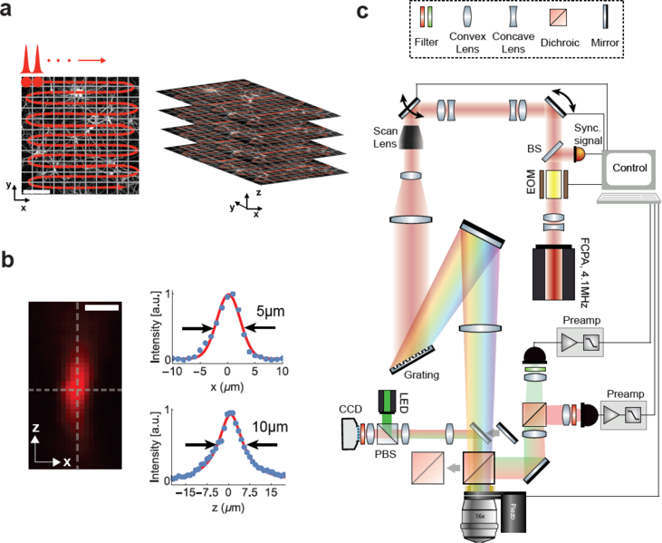
Figure 1: Schematic and principle of scanned temporal focusing imaging system. (a) Schematic of the s-TeFo imaging. A large field-of-view is raster-scanned using an enlarged sculpted PSF and a one-pulse-per voxel excitation-acquisition scheme. Volumetric image acquisition is achieved by translating the objective axially (along z-axis) via a high-speed long-range piezo. Scale bar is 100µm. (b) Measured axial confinement of the sculpted point-spread-function (PSF) of the laterally symmetric TeFo-spot using 0.5µm sized beads. Corresponding x and z profiles showing lateral and axial confinement of excitation, a.u., arbitrary units. Scale bar is 10µm. (c) Overview of the s-TeFo microscope. The main dichroic mirror and a mirror are mounted on a slide in order to switch between two-photon scanning and wide-field epi-fluorescent imaging mode. EOM, electro-optical modulator, BS, beam-splitter, PBS, polarizing beam-splitter.
File history
Click on a date/time to view the file as it appeared at that time.
| Date/Time | Thumbnail | Dimensions | User | Comment | |
|---|---|---|---|---|---|
| current | 15:00, 1 November 2016 |  | 1,043 × 855 (291 KB) | Admin (talk | contribs) | Figure 1: Schematic and principle of scanned temporal focusing imaging system. (a) Schematic of the s-TeFo imaging. A large field-of-view is raster-scanned using an enlarged sculpted PSF and a one-pulse-per voxel excitation-acquisition scheme. Volumetr... |
You cannot overwrite this file.
File usage
The following 2 pages use this file: